Know Your Device
Onboard LEDs
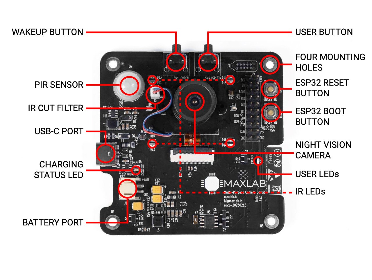
Tokay Lite is equipped with several onboard LEDs, each serving a specific purpose. Understanding their functions is essential for efficient operation and troubleshooting.
Here's a breakdown of the different LEDs on the camera:
-
Charging LED:
This LED serves as an indicator for the camera's battery charging status. When the camera is connected to a power source and is currently charging, this LED will illuminate, providing a visual cue that the charging process is in progress.
-
Charging Complete LED:
It is a companion to the Charging Ongoing LED. Once the camera's battery has been fully charged, this LED will light up, signaling that the charging process is complete. It's a convenient way to know when the camera is fully powered and ready for use.
-
User LED:
The User LED is programmatically driven by the MCU. Depending on the LED's behavior and color, it can convey various status updates, such as camera activation, connection to WiFi, or image capture.
-
Ten 850nm IR LEDs:
The camera features ten Infrared (IR) LEDs with a wavelength of 850nm. These IR LEDs are used to enable night vision and low-light image capture. When the camera switches to night mode, these IR LEDs illuminate the scene with infrared light, allowing the camera to capture images in conditions with minimal visible light. IR LEDs are driven by MCU and their behaviour can be changed.
Buttons
Tokay Lite has a few various buttons onboard, each serving a distinct purpose.
Here's an overview of the different buttons on the camera:
-
User Button:
The User Button allows you to trigger specific actions or functions programmatically. It provides flexibility for users to customize camera operations based on their preferences or specific use cases.
-
Wakeup/Power On Button:
The Wakeup/Power On Button controls the camera's power stage. Pressing this button is required to wake up the camera from standby mode if no other triggers are present.
It also serves as the means to power on the camera when it is connected to a power source first time. This button is the gateway to the camera's functionality and operation.
-
ESP32 Reset Button:
The ESP32 Reset Button is a standard reset button for the ESP32 MCU. Pressing this button initiates a power reset of the ESP32 MCU
Importantly, this button does not reset the camera's power stage.
ESP32 reset is often useful when debugging or to flash the ESP32 using the serial port.
-
ESP32 Boot Button:
The ESP32 Boot is a standard boot control for the ESP32 MCU.
By using this pin, you can control the boot mode of the ESP32, allowing you to define how the MCU initializes.
Power Management
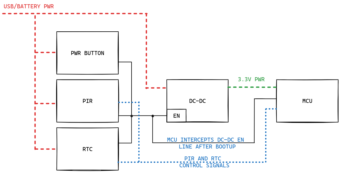
Explain power management:
- External RTC connected to the power stage - in controls DC-DC enable pin, specifically
- PIR and Wakeup button are also connected to DC-DC
- RTC, PIR and wakeup button all can be used to wakeup camera
IRCUT Switch
The IR Cut filter is an optical component that is essential for night-time operation. During the day, it allows visible light to pass through, capturing images in full color. However, at night, when infrared (IR) light is more prevalent, the IR Cut filter switches to block visible light and allows IR light to pass through. This transition is essential for achieving high-quality night vision and low-light image capture. It ensures that the camera can adapt to varying lighting conditions, providing clear and detailed images in both day and night scenarios.
The IRCUT switch is programmatically controlled by the ESP32. This control enables the camera to switch between day and night modes based on specific conditions or user preferences.
The IRCUT switch is driven by AP1511B IC.
LiPo Charger
The battery charging is implemented by PCF85063A IC.
The camera is compatible with 1-cell LiPo batteries with a JST-PH (2mm pitch). This connector type is commonly used in LiPo batteries, making it easy for users to find suitable replacement or spare batteries.
Two indication LEDs are there to provide status of charging. See LED section for more information.
USB Port
The camera is equipped with a USB-C port, which requires a minimum 1A power supply for proper operation. When you connect both the USB-C cable and the battery, the camera will automatically start charging the battery.
PIR Sensor for Motion Detection
The camera PCB contains a PIR (Passive Infrared) sensor, built on AS312 IC.
PIR sensor's purpose is to detect motion by sensing changes in infrared radiation within its field of view.
This sensor serves as a source of camera wakeup when it's in low power mode, allowing the camera to activate and capture images in response to detected motion.
The PIR sensor is connected via GPIO to the ESP32 microcontroller, enabling it to react to motion detection signals. By using the D-Latch connected to the PIR sensor, the MCU can enable or disable its operation.
When enabled, the PIR senson is also used as a wakeup source for the camera.
Ambient Light Sensor
An Ambient Light Sensor (ALS) is integrated into the camera to measure the ambient light level in its surroundings. The ALS sensor provides valuable information about the lighting conditions, enabling the camera to adjust its settings for optimal image capture.
The ALS sensor is connected via I2C to the ESP32 MCU, allowing it to communicate with the camera's control system and make real-time adjustments based on the detected ambient light levels.
Based on ALS values it is possible to switch between night and daytime camera operation.
Next Steps
If you feel you're familiar enough with the camera operation, consider jumping into the firmware development or proceed with the seelction of options from the navbar.